Have you ever wondered if the air in your bedroom or office is actually “stale”? High CO² levels can significantly impact your well-being, leading to drowsiness, headaches, and poor concentration.
In this project, we are going to build a standalone Environmental Data Logger to monitor these crucial parameters. At its core, the system uses the high-precision SCD40 photoacoustic NDIR sensor to reliably read CO² concentration (in ppm), ambient temperature, and humidity. Additionally, the BH1750 digital light sensor is used to measure the light intensity in the environment, providing a complete environmental profile.
The logger is designed to take a new set of readings CO², temperature, humidity, and light data—and store them onto an SD card, stamped with the exact time and date, every 30 seconds. We will implement a slide switch to easily turn logging on and off to prevent unwanted data points. A large red LED indicates when logging is active. Note that to ensure the light measurement is not influenced by the indicator, the LED is briefly turned off while the BH1750 takes its reading.
SCD40
Unlike cheaper air quality sensors that estimate CO₂ levels based on volatile organic compounds (VOCs), the SCD40 is a highly accurate photoacoustic NDIR (Non-Dispersive Infrared) sensor.1 It works by directly measuring the absorption of infrared light by actual CO₂ molecules, making it perfect for reliable and precise environmental monitoring in your datalogger. The sensor is pre-calibrated and communicates via the I²C protocol, providing not only CO² concentration (in ppm) but also temperature and humidity readings.
BH1750
The BH1750 is a digital ambient light intensity sensor that offers a significant upgrade over a photoresistor (LDR) for datalogging. It provides a high-resolution, 16-bit digital output directly in lux (lx), making the light measurement calibrated and easily quantifiable across a wide range. Its use of the I²C interface and available Arduino libraries ensure it is a simple, accurate, and repeatable sensor to implement in your project.
PC data transfer
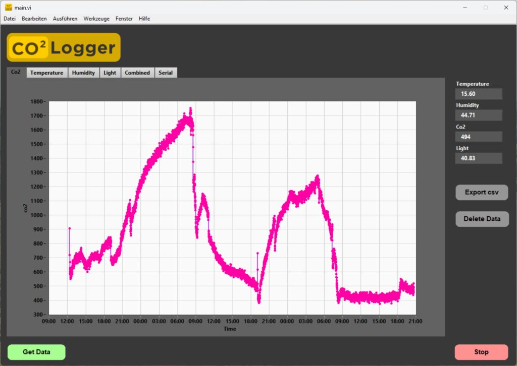
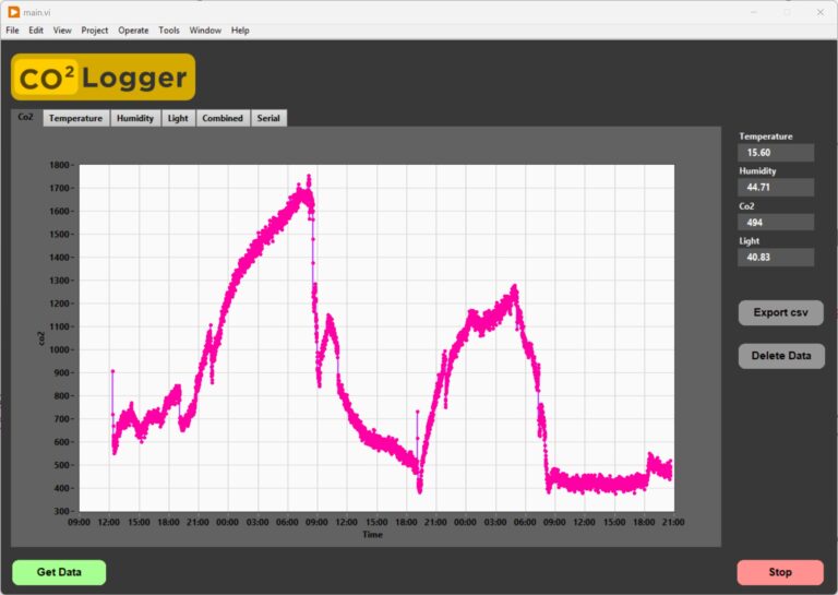
Storing all the sensor data on an SD card provides the raw information, but it has little use without a proper visualization tool. I developed a LabVIEW software application that acquires the data stored on the SD card and generates graphs from it. The software and the full LabVIEW code will be the topic of a future tutorial. The LabVIEW executable can be found here (LabVIEW Runtime required).
Component list
- Data logger shield
- Led
- 330R resistor
- Slideswitch
- Sd card
- Digital lightsensor BH1750 (breakoutboard)
- SCD40 Sensor (breakoutboard)
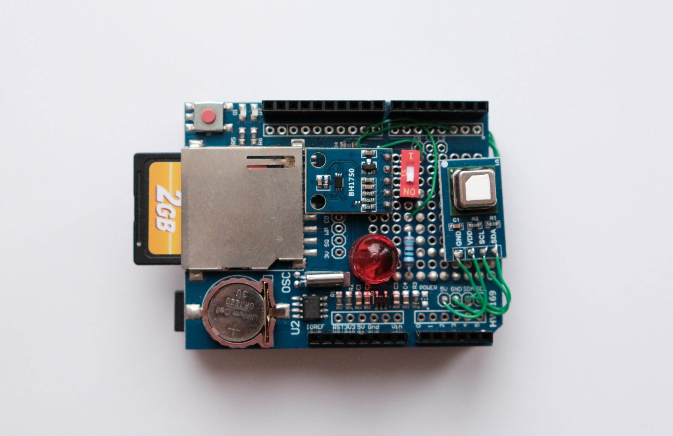
Wiring
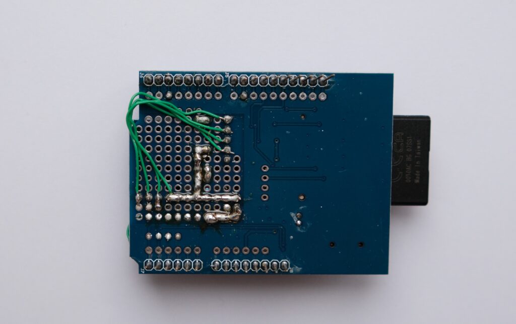
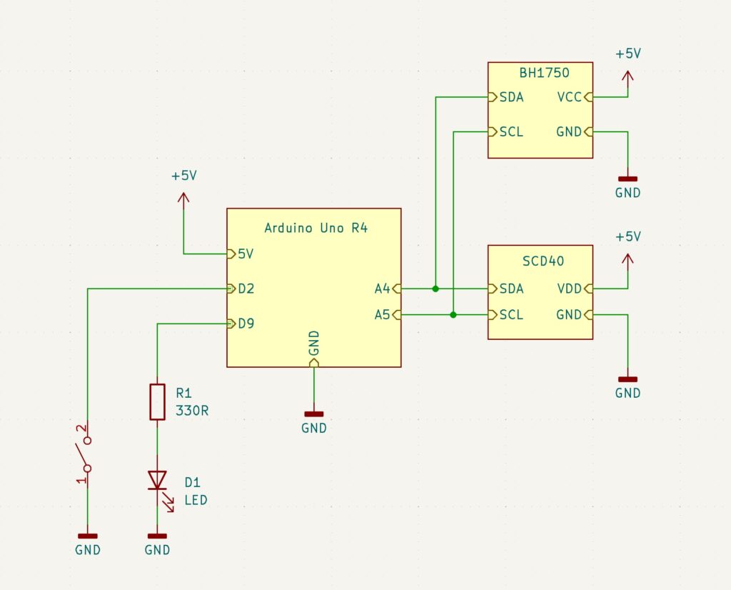
The wiring is done fairly simple. The two Sensors are connected via I²C bus to the Arduino Uno R4 and are souldered on top of thelogging shield aswell as the Led, resistor and slideswitch. For the connections a coibination of solderjoints and single core wires was used.
Code
The hole Arduino code is on Git
|
1 2 3 4 5 6 |
#include "SPI.h" #include "SD.h" #include "Wire.h" #include "RTClib.h" #include "BH1750.h" #include "SparkFun_SCD4x_Arduino_Library.h" |
All those libraries are required. They can be downloaded via the Arduino ide.
|
1 2 3 4 5 |
// Timing unsigned long lastSCD40_check = 0; unsigned long lastSCD40_checkInterval = 1000; // check every 1s if new scd40 data is avalible -> then log unsigned long lastMeasurementTrigger = 0; unsigned long MeasurementTriggerInterval = 30000; // log every 30 seconds |
In the timing segment, we set the interval at which the SCD40 is read. During testing, I noticed that reading too quickly leads to higher temperature readings. I suspect that the sensor heats up slightly each time it is read.
|
1 2 3 4 5 6 7 8 9 10 11 12 13 14 |
// Periodically trigger SCD40 measurement if (millis() - lastMeasurementTrigger >= MeasurementTriggerInterval) { scd40.measureSingleShot(); lastMeasurementTrigger = millis(); } // Periodically check if scd40 data is avalible and log data if true if (millis() - lastSCD40_check >= lastSCD40_checkInterval ){ if (scd40.readMeasurement() == true && logging_active == true){ writeDataLine(); } lastSCD40_check = millis(); } |
In the main loop(), the microcontroller uses the millis() function to precisely track the time and determine if it is time to trigger a new SCD40 measurement. When the 30-second interval has elapsed, the scd40.measure() function is called. This command tells the photoacoustic sensor to begin a multi-second measurement cycle.Once the sensor has completed its internal measurement, the data becomes ready to read. The second conditional check, typically using the scd40.readMeasurement() function, is used to poll the sensor and retrieve this new data. If this function confirms new sensor data is available (by returning true), the data is then packaged and the writeLine() function is immediately called to save the complete timestamped reading to the SD card.
|
1 2 3 4 5 6 7 8 9 10 11 12 13 14 15 16 17 18 19 20 21 22 23 24 25 26 27 28 |
void writeDataLine(){ // Read the CO2, Temperature, and Humidity values from the SCD40 sensor's internal buffer co2 = scd40.getCO2(); temperature = scd40.getTemperature(); humidity = scd40.getHumidity(); DateTime now = RTC.now(); // Get the current time from the RTC digitalWrite(status_led_pin, LOW); // Temporarily turn off the status LED to ensure it doesn't interfere with the light measurement delay(100); float lux = lightMeter.readLightLevel(); digitalWrite(status_led_pin, HIGH); // Turn the status LED back ON // Open the log file in append mode File logfile = SD.open(logFileName, FILE_WRITE); // Write the data fields in CSV format (comma-separated values) logfile.print(now.unixtime()); logfile.print(", "); logfile.print(lux); logfile.print(", "); logfile.print(co2); logfile.print(", "); logfile.print(temperature); logfile.print(", "); logfile.println(humidity); logfile.flush(); // Ensure data is immediately written to the SD card logfile.close(); // Close the file to save the data and free the SD card access } |
In the writeDataLine() function the Sensor values get aquired and stored on the sd card.
|
1 2 3 4 5 6 7 8 9 10 11 12 13 14 15 |
// Function to parse the incoming serial command and execute the corresponding action. void handleSerialCommand(String command) { if (command == "getData") {sendCSVData();} // Send all data from the SD card over serial else if (command == "getStatus"){Serial.println("logger_okay");} // Confirm the logger is operational else if (command == "getByteCount"){Serial.println(getByteCount());} // Get the file size of the log file else if (command == "getLoggingInterval"){Serial.println(MeasurementTriggerInterval);} // Print the time (in milliseconds) between measurements else if (command == "deleteData"){deleteSdData(); Serial.println("data deleted");} // Delete the log file from the SD card else if (command == "getTime"){sendUnixTime();} // Send the current RTC time as a Unix timestamp else if (command.startsWith("setTime:")){ // Expects command format: "setTime:1672531200" String timePart = command.substring(8); // Extract the timestamp string unsigned long time = timePart.toInt(); // Convert the string to an unsigned long integer setUnixTime(time); // Update the RTC with the new timestamp } } |
Another core element of the code is the handling of communication with the PC via Serial. This allows for interaction and configuration of the datalogger. In each loop cycle, the microcontroller checks if new serial data is available and begins storing it sequentially into an input buffer. Data is continually added to this buffer until a line feed character is read, which serves as the indicator that the full command message has been successfully received.Once a complete command is buffered, the handleSerialCommand() function is triggered to parse the input and perform the appropriate action. For instance, if the command getTime is received, the microcontroller reads the current time from the onboard Real-Time Clock (RTC) IC and transmits it back to the PC.The setTime command is special: it is used to synchronize the datalogger’s time with the PC. This command expects not only the instruction but also attached UTC time data, allowing the microcontroller to accurately set the RTC and ensure all subsequent log entries are correctly timestamped.